
Drain Channel Guide: Selection, Installation, Drainage, and Maintenance
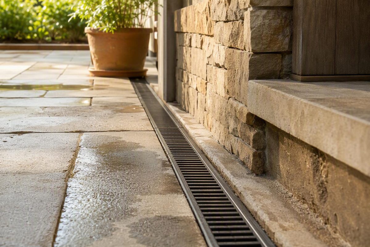
Runoff enters through a grate or slot and exits through an outlet. Passenger-vehicle systems may need concrete support. The discharge route comes first.
Overview
A drain channel is a long, narrow surface-water collection system. Runoff enters through a grate or slot, travels along the channel, and leaves through an outlet connected to downstream drainage. It is useful where water pools on hard surfaces, provided the channel, outlet, traffic rating, and discharge route suit the site.
Also called a channel drain, trench drain, or linear drainage channel, the system intercepts water across a line rather than at a single point. NDS describes channel and trench drains as systems that collect runoff and convey it to drain pipes. This makes them useful where water crosses a wide entrance or gathers along the edge of paving.
The grate or slot is the inlet. Beneath it, the channel carries collected water toward a bottom, end, or side outlet, depending on the selected system. The outlet then connects to a pipe, catch basin, or larger drainage arrangement. According to JDP’s basic guide to channel drainage, a grate can also keep larger debris out while remaining removable so smaller material can be cleared from the channel.
A drain channel is therefore only one part of the water path. It cannot compensate for an undersized outlet, blocked downstream pipe, unsuitable discharge destination, or installation that does not support the expected traffic. Begin by identifying where water comes from, where it crosses or collects, and where it can lawfully and physically go.
Where drain channels are useful
Drain channels are useful where runoff pools on, flows across, or needs to be intercepted at the edge of a hardscape. Typical settings include driveways, patios, walkways, pool surrounds, parking areas, gardens, and turf interfaces, all applications identified in ABT Drains’ channel-drain guide.
On a driveway, a channel can intercept water moving toward a garage, building entrance, or lower section of pavement. On a patio or pool surround, it can collect water along a boundary or across the surface. On a walkway, the objective may be to reduce standing water in the path of pedestrians. In a parking or commercial area, the same collection principle applies, but traffic loading and installation support become more demanding selection factors.
Capturing and conveying runoff may reduce conditions associated with persistent surface water. A Lowe’s listing for an NDS slim channel kit describes the intended benefits as reducing mildew growth, concrete staining, and damage by carrying excess water downstream. Those are possible benefits, not guaranteed outcomes. Results still depend on collecting enough runoff and maintaining an open route to an adequate outlet.
A channel drain is not automatically the right answer whenever water is present. If the problem comes from a leaking pipe, groundwater, an overflowing roof system, or runoff entering from outside the area being considered, a surface channel may address only the visible symptom. Confirm the source and direction of flow before choosing the interception line.
How to choose a drain channel
Choose a drain channel as a complete system, not by channel width or grate appearance alone. NDS identifies runoff, automobile traffic, and application as selection factors. You must also consider the inlet, channel body, outlet, downstream pipe, access for cleaning, and the support required around the installed system.
The following matrix is an initial screening tool. It does not assign load classes or hydraulic capacities because those depend on the applicable standard, actual runoff, and manufacturer documentation.
| Application | Runoff and traffic screen | Channel and grate focus | Outlet and access focus | Installation verification |
|---|---|---|---|---|
| Pedestrian area or walkway | Identify water crossing the walking route and any equipment that may also pass over it | Select openings and a grate arrangement appropriate for the intended surface use; keep the cover removable where cleaning is required | Provide an accessible outlet path and a way to remove collected debris | Verify finished elevation, grate security, surrounding paving support, and the selected product’s stated use |
| Patio or pool area | Consider the paved area contributing runoff and where water currently collects | Compare a visible grated channel with a narrower slot arrangement; account for the slot’s lower inlet flow | Keep cleanout points reachable after paving and verify the downstream connection | Follow the manual for channel support, joints, surface level, and any required sealant |
| Residential driveway | Account for both runoff and passenger-vehicle loading | Verify that the channel, grate, and installed assembly are suitable for vehicle crossings | Check outlet position, pipe connection, and access without relying on the grate alone as a sediment-control system | Confirm the required concrete installation; RELN conditions passenger-vehicle support on appropriate installation in concrete |
| Commercial traffic area | Treat traffic, slab construction, and runoff as project-specific design inputs | Use the governing regional standard and the selected system’s documented channel and grate suitability | Coordinate outlets, catch basins, sediment control, pipework, and maintainable access | Obtain the product-specific concrete surround, anchoring, joint, and slab details from the manufacturer and project designer |
Traffic terminology requires particular care. The supplied installation sources refer to different regional class systems, including AS 3996 and DIN classes. Those systems should not be treated as interchangeable. Verify the standard that governs the project, then confirm that the channel, grate, fasteners, surrounding concrete, and slab detail form a suitable assembly under that standard.
Vehicle-load claims can also depend on installation. A product described as suitable for passenger vehicles may require concrete support to achieve that use. The correct practical question is not merely “Is this grate strong enough?” It is “Does the documented, fully installed system suit the expected traffic and slab arrangement?”
Channel, grate, material, width, and outlet options
Physical options affect how much surface water can enter, where the system fits, how it connects, and how it can be maintained. Compare exact manufacturer specifications rather than treating every linear drainage channel as equivalent.
Channel bodies are available in different widths and depths. For example, NDS lists channel systems in 3-, 5-, 8-, and 12-inch widths. These figures illustrate product variation, but width alone does not establish capacity. Internal geometry, channel length, slope, grate opening, outlet arrangement, and downstream restriction also matter.
Grates vary in opening pattern, appearance, fastening method, and intended traffic use. A removable grate provides direct access for clearing material that passes through the openings. Larger openings may admit more debris, while a more restrictive inlet can limit how quickly water enters. Use published inlet and load information for the exact grate and channel combination where those values are available.
Material choices also vary across product families. The supplied sources include plastic and polymer-concrete systems, but they do not establish a universal rule for choosing material by chemical exposure, climate, or corrosion risk. Match the material to the manufacturer’s documented application and obtain project-specific guidance where unusual liquids or exposure conditions are present. The ACO installation manual, for example, calls for a suitable chemically resistant sealant where corrosive liquids are collected.
Outlet arrangements can include bottom, end, horizontal, or vertical connections, sometimes through an in-line pit or catch basin. Connections are product-specific. One NDS kit listing, for example, specifies bottom and knock-out outlets for 1½-inch Schedule 40 pipe. That detail applies to the listed kit, not to drain channels generally.
Slot drain vs. standard grated channel drain
A slot drain is preferable when a narrow, less conspicuous surface opening is important and its inlet performance is adequate for the site. A standard grated channel is generally easier to inspect through a broad removable cover and can admit water through a larger open area.
ABT Drains notes that slot drainage is often selected for a more inconspicuous appearance. The tradeoff is that a narrow opening can restrict inflow. JDP states that slot channels have a lower flow rate than standard channel drains because less water can pass through the opening at one time.
A conventional channel drain uses a grate over a wider channel opening. The grate can intercept larger debris, although performance depends on its hole pattern. Material that passes through may collect inside, so removable access is valuable for cleaning. A slot system also needs a planned cleanout method because its narrow surface opening can make the channel less directly accessible.
Do not select between the two arrangements by appearance alone. Compare the expected runoff, verified inlet data, debris conditions, cleaning access, traffic suitability, and manufacturer installation details. The supplied evidence does not support a universal structural comparison between slot and grated systems.
Runoff and outlet capacity: what must be calculated
Required capacity depends on the water reaching the drain and the ability of every stage to pass it downstream. Relevant inputs include rainfall intensity, contributing catchment area, surface slope, grate inlet capacity, channel flow, outlet capacity, and the capacity of connected pipework.
A listed channel flow rate does not complete that calculation. SiteOne’s trench-drain category, for example, contains products associated with figures including 16.64, 27, 51, 72, and 86.88 gallons per minute. These values show substantial product variation, but they cannot determine whether a system suits a particular site without matching the rating to the product configuration and expected runoff.
The supplied evidence does not provide a dependable universal formula for converting rainfall, catchment area, and surface conditions into a selected grate, channel, and outlet. For a preliminary brief, document the contributing surfaces, low points, drainage run, possible outlet location, and expected traffic. Then use the applicable drainage method, local rainfall inputs, and verified manufacturer performance data. Where overflow could damage a building, affect another property, or create a hazardous traffic condition, sizing should be completed by qualified local input rather than inferred from channel width.
Installation layout and connection
Installation should begin with the discharge point because the outlet establishes where the channel run must lead. Manufacturer manuals from ACO, Hubbell POLYCAST, and MIFAB describe outlet-first layouts using alignment references, secured channels, and product-specific concrete support.
At a planning level, the sequence is:
- Establish the physical and permitted discharge route.
- Locate the outlet, pipe stub, in-line pit, or catch basin.
- Lay out the channel run from the discharge end.
- Set alignment and finished elevation with the method specified by the manual.
- Connect channel sections, end components, and outlet fittings.
- Secure the system against movement or flotation before placing concrete.
- Complete the surrounding surface, allow specified curing, and test the route.
If a catch basin is used, both the Hubbell and MIFAB guides place it near the discharge piping and begin channel installation from that end. Directional arrows, numbered channel depths, or male and female ends must follow the selected system’s instructions. Do not assume that sections from different families connect or fall in the same direction.
The channel-to-pipe connection may use a manufactured outlet, a cutout, or an opening prepared for the required pipe. The ACO manual describes direct vertical or horizontal outlets and connections through an in-line pit, with an appropriate sealant or adhesive for the prepared opening. Follow the exact cutting and sealing method for the channel or basin material.
Drain-channel system parts checklist
Account for every component between the surface inlet and the downstream drainage before excavation begins. The exact bill of materials varies by product and layout, but a practical checklist includes:
- Channel bodies in the required sequence and length
- Compatible grates, locking devices, or removable covers
- End caps, end outlets, bottom outlets, and junction pieces where needed
- An in-line pit or catch basin if the layout calls for one
- A debris strainer, rubbish basket, or other specified sediment-control component
- Product-compatible pipe fittings, adapters, sealant, or adhesive
- Downstream pipework leading to the confirmed discharge point
Also account for the manufacturer’s alignment and anchoring components. These can include installation chairs, brackets, rebar, threaded rods, or other devices that hold the channel at the required elevation during concrete placement. The MIFAB guide uses rebar or threaded rod to resist flotation, while the Hubbell POLYCAST guide describes chairs, clamps, and rebar for alignment and stability.
Check compatibility before purchase. A grate that fits the nominal width may still have a different fastening system or intended loading, and an outlet may require a specific channel location or pipe size.
Does a drain channel need a fall?
A drain channel does not always need to slope. JDP explains that a level channel can function when it has a suitable outlet at its base because flowing water moves to that low exit point. The outlet and downstream route still need enough capacity and must remain clear.
A modest fall can improve movement through the run and help water and sediment travel toward the outlet. For the sloped system described in its installation manual, ACO gives an example of 5 millimetres of fall per metre. That is a source-specific general recommendation, not a universal installation rule. Confirm the required fall, tolerances, and outlet position in the selected product manual.
Pre-sloped channel systems provide another option. NDS lists a 0.7% built-slope system for flat areas. Other systems may be neutral, stepped, or assembled from numbered sections. The surrounding surface must still direct runoff toward the inlet. Sloping the channel cannot collect water that remains trapped elsewhere on the paving.
Excavation, concrete surround, finished elevation, and commissioning
Excavation must provide space for the channel, outlet components, alignment hardware, and the specified concrete surround. These dimensions depend on the product, expected load, slab design, and governing standard. Do not transfer a clearance or concrete detail from one manual to an unrelated system.
For example, the Hubbell POLYCAST installation guide specifies at least 4 inches of concrete beneath and on both sides of the described system, or an amount equal to slab thickness where that is greater, with consultation from the slab designer. By contrast, the ACO manual gives different encasement dimensions for its system according to AS 3996 classes. These are product and standard-specific instructions, not universal trench-drain dimensions.
Before setting channels, remove loose material and prepare the base as the selected manual requires. Alignment strings can establish the channel edge and finished elevation over the run. Anchoring matters because an unsecured channel can move or float while concrete is poured. MIFAB’s guide calls for polymer-concrete channels to be anchored with rebar or threaded rod and instructs installers to pour concrete evenly on both sides.
Finished elevation is also system-specific. The ACO manual illustrates the adjacent finished surface 3 millimetres above its channel. The MIFAB guide places its channels approximately ⅛ inch below finished floor elevation. Both examples reinforce the same planning point: use the chosen manufacturer’s elevation detail so surface water reaches the inlet without leaving an unintended obstruction.
Coordinate joints with the slab design. The Hubbell guide includes particular instructions for parallel and intersecting expansion joints, while ACO discusses sealing where collected liquids require it. Joint location, movement accommodation, and sealant are therefore not details to improvise after the channel is fixed.
Before concrete placement, confirm alignment, channel sequence, outlet connection, end caps, anchoring, and any measures used to keep concrete or debris out of the channel. Follow the specified placement and curing process before installing or loading the grates.
Commissioning should verify the entire water path. The ACO manual instructs installers to remove debris from the channel and grate rebate, confirm that outlet pipes are clear, install strainers or baskets where required, and flush the system to identify pipework blockages. The practical goal is to find a blocked or misconnected route before the installation is treated as complete.
Confirm the discharge route and local requirements
A physical outlet is not the same as an approved discharge destination. Before excavation, identify where the water will leave the channel, how it will reach that point, and which local authority, drainage code, property restriction, or project requirement governs the connection.
Manufacturer documentation can show how to connect a channel to a vertical outlet, horizontal outlet, in-line pit, catch basin, or downstream pipe. The ACO installation manual, for example, describes those physical connection arrangements. It does not establish whether a particular destination is lawful for every property or jurisdiction.
Verify whether the proposed route may connect to the intended drainage system, discharge elsewhere on the property, or requires approval. Also check whether runoff may cross a property boundary, affect neighbouring land, or enter a system that does not accept surface water. The supplied evidence does not establish universal permit rules, lawful destinations, or professional-design triggers.
Professional input is appropriate when sizing cannot be verified from complete site and product data, when the channel interacts with a structural slab, when traffic loading is significant, or when the discharge route is unresolved. Local drainage professionals, project designers, manufacturers, and relevant authorities answer different parts of that question. Obtain the applicable requirements before buying components that depend on an unconfirmed outlet.
Cleaning, inspection, and grate safety
A drain channel should be cleaned often enough to keep the inlet, channel, outlet, and downstream pipe open. The required frequency depends on local debris and use, so inspect after conditions likely to carry leaves, sediment, or other material into the system rather than relying on an unsupported fixed interval.
A practical maintenance cycle is:
- Remove surface debris from the grate or slot.
- Lift removable grates using the product’s intended method.
- Clear sediment and smaller debris from the channel.
- Inspect the outlet, catch basin, strainer, or basket.
- Flush the system when needed and confirm that water reaches the downstream route.
- Reinstall and secure the grate, replacing damaged components as required.
JDP notes that removable grates both block larger debris and allow material inside the channel to be removed. A listed NDS slim-channel kit similarly uses snap-in slotted grates to provide cleanout access. A removable cover is useful only if landscaping, paving, or fixtures do not block access after installation.
Do not stop at cleaning the visible inlet. ABT Drains warns that neglected debris can clog connected pipework. If water remains in the channel or drains slowly after cleaning, inspect the outlet and downstream route rather than assuming the channel itself is too small.
Grates are also walking or driving surfaces. Inspect for loose, broken, displaced, or incorrectly fastened sections whenever the channel is opened. ABT identifies broken or loose grates as a maintenance hazard. Refit locking devices according to the product instructions and do not continue loading a damaged assembly simply because water can still enter it.
What affects drain-channel cost
Drain-channel cost depends on more than the visible length of channel. The channel body, grate material, width, depth, traffic suitability, outlets, end caps, junctions, catch basins, fittings, anchoring hardware, sealants, and downstream pipework all affect component cost. Excavation, concrete, slab joints, surface restoration, labour, design, and permitting can add separate project costs.
Retail listings show why a single product price is not a dependable installation estimate. At the time represented by the supplied evidence, Home Depot’s channel-drain category stated that channel-drain products ranged from $10 to $2,000. Drainage Direct listed one 4-foot Polylok channel with a ductile grate at $199. These are retail component snapshots, not comparable installed-system quotes.
Prices can also vary by location and availability. SiteOne states that local branch prices may differ from displayed prices and that inventory is not guaranteed. A defensible budget therefore requires an itemized layout and local pricing for the exact system.
Compare quotations using the same scope: channel length, grate specification, outlet arrangement, downstream connection, concrete support, excavation, disposal, restoration, and testing. The supplied evidence does not support a reliable universal installed-cost range. It supports only the conclusion that component prices vary widely and must be separated from the full cost of a correctly connected and supported drain-channel installation.