
Pipe and Clamp Selection: Types, Sizing, Materials, and Installation Checks
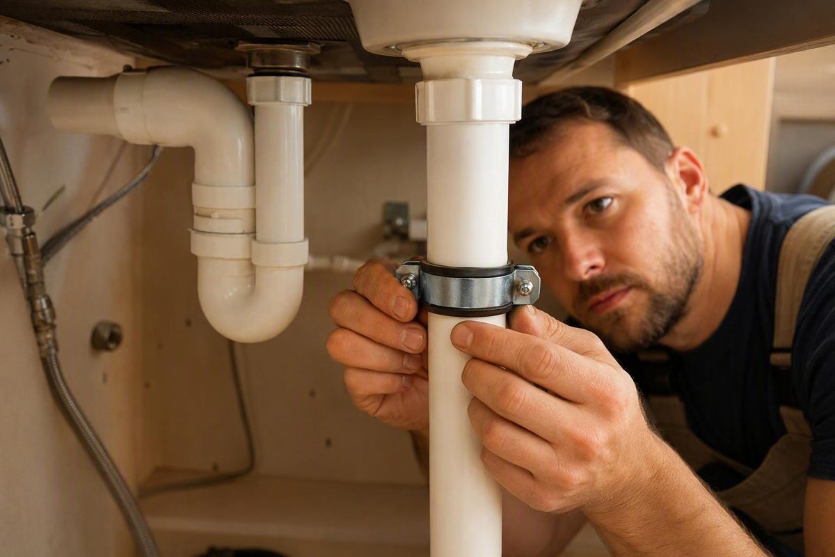
Identify the product family first, then match actual dimensions, support arrangement, material, environment and installation requirements.
Overview
A pipe and clamp system normally uses a clamp to secure, support, position, or align piping. Choosing one requires you to identify the product family first, then match the pipe dimensions, support arrangement, material, environment, and installation requirements to the manufacturer’s specifications and any governing project or code requirements.
The terminology needs attention because “pipe clamp” can describe fundamentally different products. It may mean plumbing hardware that fixes tubing to a surface, a support for vertical or horizontal piping, a connector between round structural members, a rated rigging component, or a woodworking tool whose jaws slide on a replaceable pipe. PipingNow describes pipe clamps as hardware for securing, supporting, or positioning pipe, while Grainger uses the same term for woodworking jaws mounted on user-supplied pipe.
For a plumbing or maintenance purchase, work through four decisions in order: identify what the clamp must do, establish the pipe’s actual dimensional convention, choose materials compatible with the pipe and environment, and verify spacing, attachment, load, and movement requirements. A nominal size or familiar-looking clamp shape is not enough to establish compatibility.
Choose the Pipe-Clamp Family Before Comparing Products
Begin with the physical task. Products in different pipe-clamp families may share similar names but are not interchangeable. The following decision matrix separates the primary meanings supported by the available product documentation.
| Product family | What it acts on | Primary selection cues | What to verify |
|---|---|---|---|
| Pipe-support clamp | Pipe or tubing that must be secured, supported, positioned, or aligned | Pipe size, support orientation, mounting surface or channel, material, and environment | Compatible pipe dimensions, mounting geometry, fasteners, support rating, spacing, and permitted movement |
| Pipe-to-pipe clamp | Two round structural members | Outside-diameter range, member orientation, connection geometry, and product rating | Both members’ OD, supported configuration, hardware, and documented capacity |
| Woodworking pipe clamp | A workpiece held between jaws that slide on pipe | Compatible slide-bar pipe, clamping force, jaw arrangement, and required working length | Required pipe specification and the clamp maker’s compatibility information |
| Rigging or staging clamp | Pipe or truss used in a specialized rigging structure | Exact clamp or coupler family, member dimensions, connection configuration, and rating | Manufacturer documentation, applicable requirements, and rated use for the complete assembly |
A pipe-support clamp is the usual family when the job is to hold plumbing against a mounting surface or within a support system. One standard product listing, for example, describes clamps intended to secure tubing to mounting surfaces and suitable for most copper, PEX, and CPVC piping systems. That statement applies to the listed product, not automatically to every clamp of the same nominal size. See the Oatey standard pipe-clamp listing.
Specialized exhaust and telecommunications listings may also use pipe, bracket, or clamp terminology. Treat those labels as a cue to consult the product’s own dimensional and application data, not as evidence that the hardware is suitable for plumbing, structural support, or rigging.
Woodworking Pipe Clamps
A woodworking pipe clamp does not normally support installed piping. It consists of two jaws attached to a user-supplied length of pipe, with that pipe functioning as the jaws’ slide bar. Changing the pipe length changes the tool’s available working span, subject to the clamp manufacturer’s pipe-compatibility requirements. Grainger describes this jaw-and-slide-bar arrangement and categorizes products by compatible pipe size and clamping force.
This distinction prevents a basic purchasing error. If you need to secure a water line, the pipe is the supported object. If you need to hold boards or another workpiece, the pipe is part of the clamping tool. The relevant dimensions, forces, attachments, and installation checks differ accordingly.
Pipe-to-Pipe and Rigging Clamps
A pipe-to-pipe clamp connects round members rather than attaching an ordinary plumbing line to a wall, joist, or channel. Product listings demonstrate why OD is central to this family: one connector is described for joining two members from 1-1/2 to 3-1/2 inches OD, while another covers two members from 2-3/8 to 5 inches OD. Those ranges appear in Tessco’s structural pipe-to-pipe clamp category.
Both members therefore need to fall within the selected connector’s documented OD range. You must also confirm the permitted orientation and complete connection geometry rather than assuming that any pipe-to-pipe clamp can form every parallel or 90-degree joint.
Rigging suppliers use the category for specialized hardware such as cheeseboros, rota locks, gridlocks, and offset clamps. Stage Rigging Warehouse lists those families under steel pipe clamps and couplers. A category name alone does not establish a safe working load or approved use. For lifting, overhead, staging, or other load-critical work, use the exact rated documentation and applicable project requirements for the complete assembly.
Pipe-Support Clamp Types and Selection Cues
Support-clamp labels describe different geometries and mounting arrangements. The available product range includes standard, riser, strut, offset, extended, and C-clamps, according to PipingNow’s pipe and strut clamp category. These names narrow the search, but the name by itself does not determine pipe compatibility, clearance, capacity, or attachment requirements.
A standard pipe clamp is the starting category when pipe or tubing must be fixed to a mounting surface. The actual product must still be checked against the pipe material and dimensions. For example, a standard clamp advertised for copper, PEX, and CPVC establishes compatibility only for that documented product and its stated size range.
A riser clamp points to a vertical-run support configuration. The useful selection question is not merely whether the pipe is vertical, but how the selected clamp bears on the structure and how that assembly is intended to support or restrain the run. The product documentation and project design must resolve those details.
A strut clamp belongs to a channel-based support arrangement. It is relevant when the pipe will be mounted to compatible strut rather than directly to an ordinary surface. Confirm the clamp-to-channel interface, the pipe dimension, the channel arrangement, and every required fastener as one support assembly.
Offset and extended clamps provide geometry for applications where the pipe requires separation from a surface or must clear an obstruction. A greater-looking offset is not proof of sufficient clearance or capacity. Compare the manufacturer’s standoff, dimensional drawing, mounting-hole arrangement, and rating with the actual installation.
A C-clamp is another documented category label, but the supplied evidence does not establish one universal application rule for every C-clamp product. Use the name to locate the appropriate family, then rely on the selected manufacturer’s description and drawings.
The practical rule across these types is consistent: first match the pipe size, then choose the clamp according to how the pipe will be supported. Installation location, material requirement, and support-system type also affect the choice, as PipingNow’s selection guidance explains. Do not use subtype names as substitutes for dimensional, mounting, or load verification.
Match the Clamp to the Pipe and Mounting Arrangement
Correct pipe and clamp sizing starts with the pipe, not the number printed in a category title. Pipe material, sizing system, actual diameter, liner, and support configuration can all affect whether a clamp fits and functions as intended. Water-supply pipe may be identified using Copper Tube Size, or CTS, while gas and drain pipe may use Iron Pipe Size, or IPS, according to Contractor Magazine’s discussion of pipe-support sizing.
Use the following workflow to build a defensible product shortlist:
-
Identify the pipe material and service. Record whether the pipe is copper, PEX, CPVC, another plastic, steel, or another documented material. Material affects the applicable sizing convention, support design, movement, and compatibility.
-
Record every relevant size marking. Note the nominal pipe or tube size, schedule or wall designation when available, and whether the system is identified as CTS, IPS, or another convention.
-
Measure the dimension the listing actually requests. If the product is selected by outside diameter, measure OD. If a listing specifies clamp ID, compatible pipe size, or another dimension, interpret that label using the manufacturer’s drawing and instructions.
-
Define the support arrangement. Establish whether the clamp will mount to a surface, channel system, vertical support, or another round member. Include necessary standoff and obstruction clearance.
-
Account for the complete clamp geometry. Check whether a liner, cushion, or insulating body occupies space around the pipe. Confirm the mounting holes, bracket dimensions, and required fastener arrangement.
-
Verify the selected item in its documentation. Confirm compatible pipe material and size, dimensional range, mounting configuration, and any stated limits before ordering or installation.
This process also applies when replacing an existing clamp. Matching the old clamp’s nominal label is less reliable than identifying the pipe, measuring the required dimension, and comparing the replacement’s complete dimensional specification.
Nominal Pipe Size, OD, ID, CTS, and IPS
Nominal Pipe Size, or NPS, is a pipe-sizing designation. OD is the measured outside diameter, while ID is the internal diameter. These labels do not mean the same thing, and a nominal number should not be assumed to equal either measured diameter.
CTS and IPS add another layer of interpretation. The Contractor Magazine support guide distinguishes water-supply pipe identified as CTS from gas and drain pipe treated as IPS. It also notes that a one-inch copper or CPVC pipe can require a different hanger type and size from a comparably labelled gas pipe because diameter, wall thickness, pipe material, and load differ.
Commercial listings confirm that clamp dimensions are not expressed through one universal field. A structural connector may specify the OD range of both members. A woodworking clamp may state a compatible pipe size. Another supplier may label a product by clamp ID, as shown by Würth USA’s “Pipe Clamp I.D. 10X12 Wide” listing. Read the field label before comparing the number.
The useful question is therefore not “What clamp matches a one-inch pipe?” It is “What does one inch designate for this pipe, and which physical dimension does this clamp require?” Answering both parts prevents a nominal-size match from being mistaken for a verified fit.
Verify the Manufacturer’s Dimensional Specification
The supplied evidence does not establish a universal conversion method from every nominal pipe size to an exact clamp dimension. Manufacturer data remains necessary because products can be listed by compatible pipe size, OD range, clamp ID, or family-specific terminology.
For each shortlisted clamp, confirm the compatible pipe type and size, allowable OD or ID, and the shape of the contact area. If the clamp has a liner or insulating body, verify whether the published dimension describes the assembled opening and whether the liner thickness is already accounted for. Then compare the mounting geometry, including standoff, hole locations, channel interface, and space required to fit the fasteners.
Do not infer cross-compatibility from appearance. A listing for a 1/2-inch standard clamp that documents use with most copper, PEX, and CPVC systems supports those stated uses for that item. It does not prove that every 1/2-inch clamp fits all three materials. The underlying Oatey listing provides the product-specific compatibility statement.
For pipe-to-pipe hardware, repeat the check for both members. For woodworking clamps, verify the slide-bar pipe specification rather than applying plumbing support dimensions. The manufacturer’s drawing and compatibility table should resolve the final fit.
Choose Materials for the Pipe and Environment
Clamp material affects environmental durability and its interaction with the pipe and fasteners. Common pipe-support categories include stainless steel, plastic, and galvanized products, according to Lowe’s pipe-support clamp category. That list identifies available material families, but it does not make one material suitable for every pipe or exposure.
Evaluate the clamp body, liner, bolts, washers, mounting hardware, and pipe as one material system. Begin by recording whether the location is dry, wet, outdoors, coastal, subject to washdown, or exposed to process chemicals. Then identify whether metal parts touch the pipe directly and whether water, condensation, seawater, or process fluid can reach the contact.
Plastic or polymer components can provide electrical separation and avoid corrosion of the polymer body itself, but performance remains product-specific. One insulating clamp described in Plumber Magazine’s pipe-support guide uses polypropylene, has a stated temperature range of 0°F to 180°F, and uses a ribbed form intended to accommodate expansion and contraction while reducing noise and vibration. Those figures and functions belong to that described product, not to all plastic clamps.
Galvanized and stainless products require equally specific checks. A coating’s presence does not establish its suitability for a given exposure, and a stainless clamp body does not remove corrosion concerns if incompatible bolts or direct contact with another metal creates a galvanic path. Confirm the exact body, coating, fastener, and liner materials rather than selecting from the broad category name alone.
Material choice also affects movement and pipe protection. The selected product should support the pipe without creating an unintended abrasive contact point, restricting movement that the system must accommodate, or introducing an unaddressed dissimilar-metal junction. These functions must be checked in the product data and installation design.
304 vs. 316 Stainless Steel
304 stainless steel is presented as a general-purpose choice for many piping and support applications, while 316 stainless steel provides added corrosion resistance for harsher environments. PipingNow specifically identifies washdown areas, coastal locations, chemical exposure, and other corrosion-priority applications as contexts favoring 316.
That distinction is a shortlist criterion, not a complete corrosion assessment. Choosing a 316 clamp body does not confirm that its bolts, washers, anchors, or connected pipe are also 316 or otherwise compatible. Likewise, a general-purpose 304 body still needs to be checked against moisture, chemicals, cleaning conditions, and the project specification.
When exposure is mild and the documentation permits it, 304 may meet the stated material requirement. Where coastal salt, frequent washdown, chemical contact, or a similarly harsh environment increases corrosion concerns, investigate a documented 316 option. In either case, verify the full material designation and all contacting hardware rather than relying on the word “stainless.”
Dissimilar Metals and Galvanic Isolation
Galvanic corrosion requires three conditions: dissimilar metals, an electrical connection between them, and an electrolyte such as water, condensation, seawater, or process fluid. WeiQue’s galvanic-compatibility guide states those conditions explicitly. Removing the conductive contact is therefore one way to interrupt the corrosion path.
This is why the pipe, clamp body, and fasteners cannot be assessed independently. The same guide places zinc and aluminium toward the active end of its stated galvanic series, carbon steel in the middle, and copper and passive 316 stainless farther toward the noble end. Greater separation can increase concern when the metals are electrically connected in the relevant electrolyte, but the actual assembly and exposure still need product- and project-specific evaluation.
Polypropylene and polyamide clamp bodies are electrical insulators. In the assemblies described by WeiQue, those polymer bodies physically separate the metal bolt or nut from the pipe wall and break the electrical path. An all-metal clamp does not provide that separation automatically.
Where dissimilar metals would otherwise touch, the cited guidance identifies rubber or PTFE liners, isolating bushings, isolating washers or sleeves, and dielectric coatings as possible isolation measures. Each measure must remain intact at the contact points. A liner around the pipe may not resolve a separate conductive path through a bolt, bracket, or mounting surface.
Inspection should therefore cover the whole contact chain. Identify the pipe material and coating, clamp-body material, bolt and washer materials, mounting structure, environmental exposure, and any isolator. If a coating or liner is damaged during tightening or service, the intended isolation may no longer exist. Use the selected product’s compatibility documentation and any project material requirements to confirm the final combination.
Verify Spacing, Loads, Fasteners, and Required Movement
A correctly sized clamp can still be unsuitable if it is spaced incorrectly, attached to an inadequate support, loaded beyond its documented rating, or used where the pipe must move. General shopping information cannot determine those engineering and code-dependent details.
Before installing or approving a pipe and clamp assembly, complete these checks:
-
Identify the controlling requirements. Check the applicable plumbing or building code, project specification, system design, and manufacturer’s instructions for the pipe and support hardware.
-
Confirm support spacing. Use rules for the specific pipe material, diameter, and orientation. Do not transfer an interval from copper to PEX, from horizontal to vertical pipe, or from one code framework to another without verification.
-
Verify the expected load against documented ratings. Account for the supported piping and relevant service conditions using the project’s approved method. Confirm the clamp, fasteners, channel or bracket, anchors, and supporting structure as a complete load path.
-
Select and install the specified attachment hardware. Match fastener type, size, quantity, substrate, and mounting geometry to the product documentation and governing requirements.
-
Provide for required movement. Determine whether a point should support, guide, brace, or anchor the pipe. Check thermal expansion, contraction, vibration, and directional movement before tightening the assembly.
-
Confirm critical-use documentation. For overhead, rigging, gas, structural, or other load-critical applications, use rated hardware and the applicable approval or design documentation. A product-family description does not establish suitability.
This workflow defines what must be verified, but it is not a substitute for a load calculation. The evidence does not supply a universal method for calculating pipe-and-fluid weight, dynamic loads, safety factors, anchor capacity, fastener capacity, or tightening torque. Obtain those values from the applicable design documents, codes, and manufacturer specifications.
Spacing and Code Requirements
There is no single support interval for every pipe. Spacing varies with pipe material, diameter, orientation, governing code, and project specification. Published examples illustrate that variation rather than creating one universal rule.
For horizontal Schedule 40 PVC and ABS, Plumber Magazine’s summary of UPC and IPC guidance reports a general 4-foot interval across pipe diameters. CPVC support spacing must be verified against the applicable code, project specification, and manufacturer instructions. These figures are code-summary examples and must be checked against the requirements controlling the actual installation.
The contrast becomes clearer with other materials. The cited guide distinguishes among materials, while its PEX examples include 32 inches under the IPC for sizes through 1-1/4 inches. It also describes differences between IPC and UPC thresholds for larger PEX. This variation is why neither a single clamp package nor a generic spacing chart should be applied across materials without checking its stated scope.
Orientation matters as well. Vertical support spacing, guides, and expansion provisions must be verified for the specific material, applicable code, and project requirements. A guide, support, brace, and anchor do not necessarily perform the same restraint function.
Use current requirements for the installation’s jurisdiction and project, plus the pipe and support manufacturers’ instructions. The source itself characterizes its intervals as general reference guidance and notes that engineering specifications may impose particular installation instructions.
Load, Vibration, Bracing, and Thermal Movement
Working-load values are product-specific. One CTS J-hook discussed by Plumber Magazine has a stated safe working load of 50 pounds, but that figure belongs to the identified product. It must not be transferred to another hook, clamp, fastener, anchor, or complete support assembly.
The support must be evaluated as a load path. A clamp rating alone does not establish the capacity of its screw, channel, bracket, anchor, wall, joist, or other supporting structure. Nor does the supplied evidence provide a general method for combining static pipe weight with contents, shock, vibration, or other dynamic effects. Verify every component using the applicable design basis and documentation.
Movement is a separate design issue. Contractor Magazine identifies pipe material, pipe length, and temperature differential as three main factors affecting thermal expansion. It also explains that hangers, brackets, and clamps may need to allow movement so the piping system can accommodate expansion and contraction cycles. An oversized or poorly selected support can permit unwanted movement and noise, while an overly restrictive arrangement can interfere with required movement.
Bracing and anchoring must not be treated as synonyms for ordinary support. The Plumber Magazine guide describes sway bracing as a way to control vibration, absorb shock loading, guide or restrain thermally induced movement, and resist sway. It separately identifies anchors as restraints against axial movement in drainage piping. The source also cites sway bracing at directional changes greater than 45 degrees for pipe sizes of 4 inches and larger, but that example remains subject to the applicable code and project specification.
Before approval, determine which locations are intended to carry weight, permit sliding, guide lateral movement, restrain axial movement, or resist vibration and sway. Then verify that each selected clamp, fastener, anchor, and support point has documentation for that assigned function and the expected conditions.