
Essential Principles for Thrust Restraint in Buried Pressure Pipelines
This is a general engineering guide to buried pipeline thrust restraint, not a clause-by-clause SANS compliance article. The evidence available here does not…
By Miles Carver ·
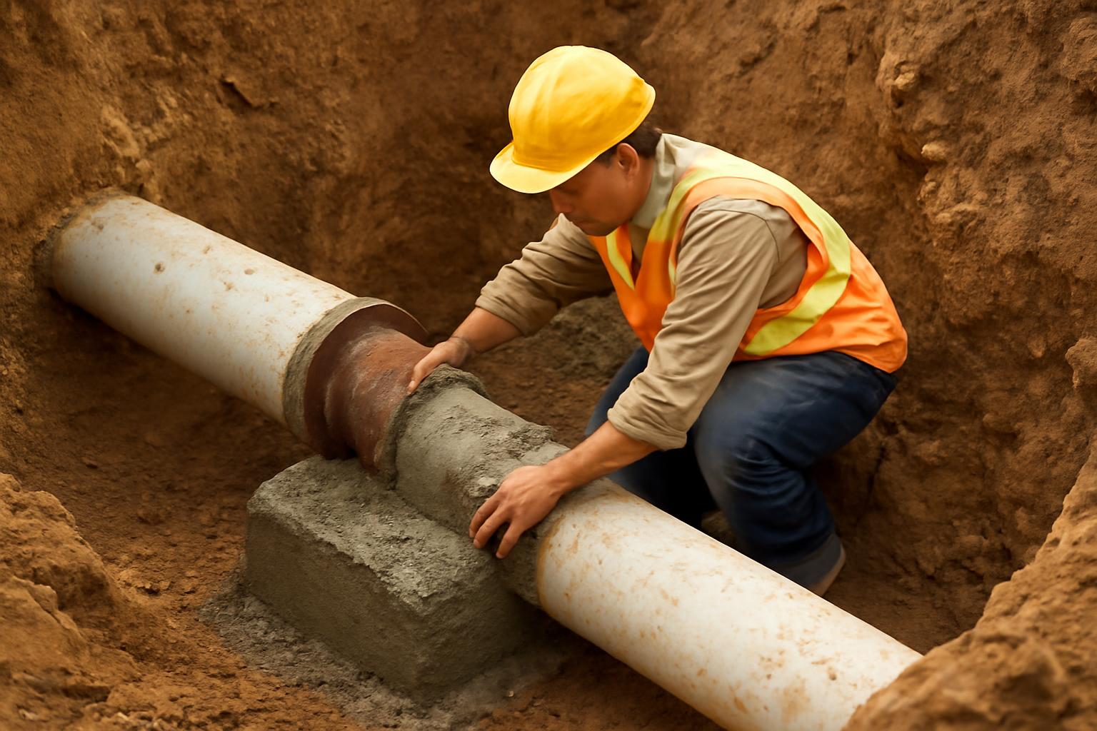
This is a general engineering guide to buried pipeline thrust restraint, not a clause-by-clause SANS compliance article. The evidence available here does not include the controlling South African standards text for thrust blocks or pipe supports, so the article cannot quote SANS requirements or certify compliance. What it can do, responsibly, is explain the design logic that sits underneath most buried thrust-restraint work, show how published utility details calculate and size restraint, and make clear when project-specific structural or geotechnical design takes over.
That scope matters. The search phrase that brings many readers here mentions both thrust blocks and pipe supports under SANS. The evidence pack, however, is strong on buried pressurized-pipeline thrust restraint and weak on prescriptive aboveground support criteria. So the article focuses on what can be supported: thrust in buried pressure pipelines, the block-or-restraint systems used to resist it, and the decision points that tell you when a standard detail stops being enough.
That still leaves an important practical bridge to “pipe supports.” Aboveground or partly supported pipe still experiences thrust when the flow path changes direction or effective pressure area. What changes is the resisting mechanism. A buried thrust block works by pushing against surrounding soil. Because the evidence here does not provide support spans, anchor forces, or SANS support detailing, this article treats supports only at that conceptual level and stops short of unsupported prescription.
For engineers and utility designers, the takeaway is that thrust restraint is a pressure-soil-geometry problem first, and only secondarily a concrete-detail problem. For homeowners and small-site owners, the same topic is a useful reminder that failures at buried tees, valves, bends, and service transitions are not ordinary DIY plumbing defects. They involve stored energy, soil behavior, and load paths that should be checked by qualified utility or civil professionals.
Understanding Thrust Forces in Pressurized Pipelines
Thrust forces develop wherever a pressurized pipeline changes direction or changes effective pressure area. In practice, that means bends, tees, reducers, plugs, caps, valves, and dead ends. At those locations the internal pressure is no longer balanced equally in all directions, so the fitting tries to move and adjacent joints can separate if nothing restrains the load (DIPRA thrust-restraint overview).
That basic description is simple, but it is worth slowing down on what is actually happening. In a straight run of pressure pipe, the internal force field is largely self-balancing along the axis of the line. Once the pipe turns, branches, closes off, or changes diameter, the geometry creates an unbalanced resultant.
Most design methods treat the dominant load as hydrostatic thrust produced by internal pressure acting on an unbalanced area. Some guidance distinguishes hydrostatic and hydrodynamic effects, but for buried utility restraint the practical design concern is the same: transient events can push the demand above the steady operating case. The WSSC design manual specifically treats design pressure as total internal pressure including transient effects rather than a casual “normal” number. That is why pressure selection for restraint design has to consider testing, commissioning, and surge, not just routine operation (WSSC design manual).
This is also why pressure mains behave differently from gravity drains and sewers. A gravity bend may need bedding and settlement control. A pressure bend may actively try to pull itself apart. If the joint beside the fitting has little longitudinal capacity, the pipe does not “stay put” just because it is underground. It stays put only if the restraint system mobilizes enough resistance, in the right direction, before movement becomes damaging.
The same principle explains why one standard detail does not fit every installation. A small fitting in good native soil with room behind it may be an ideal thrust-block situation. A congested corridor with trench spoil, nearby ducts, shallow cover, or future excavation risk may not be. In those cases the right question is not “What block does the standard drawing show?” but “What resisting mechanism will still exist after construction, testing, and future maintenance?”
That distinction matters even more when readers ask about “pipe supports.” The evidence here supports one narrow but important statement: aboveground pipelines can also experience thrust, because thrust comes from pressure and geometry, not from burial. What burial changes is the way the system resists that thrust. So whenever the line is on supports, in a chamber, on a bridge, or partly exposed, the designer has to stop thinking only in terms of block bearing on soil and start thinking in terms of structural load path, controlled movement, and foundation reaction. The evidence pack does not supply prescriptive support criteria, so this article will not invent them.
Calculating Thrust Forces for Common Fittings
For preliminary buried-pipeline design, the commonly used formulas are straightforward. For bends, a standard expression is F = 2 · P · A · sin(θ/2), where P is the governing pressure, A is the effective pressure area, and θ is the bend angle. For plugs and caps, F = P · A. For tees, thrust is commonly taken as pressure times the branch area. For reducers, it is pressure times the difference between the large-end and small-end areas (WSSC thrust-restraint design manual).
Those equations are easy to memorize and easy to misuse. The first common mistake is pressure selection. If the system is tested or commissioned at a pressure above routine operation, the higher case may govern the restraint. The second common mistake is area selection. The WSSC guidance notes that the area basis may be the pipe outside diameter or the sealing diameter depending on the connection being evaluated, so the “A” in the formula is not always the nominal bore that seems obvious at first glance. The third mistake is unit inconsistency. Pressure and area must be in compatible units or the resulting force is meaningless.
Bends get the most attention because the formula includes angle, but tees, dead ends, and reducers are often where surprises happen in the field. A dead end is conceptually simple, yet it concentrates the full pressure thrust over the closing area. A tee can look stable in plan but still impose a substantial branch thrust. A reducer introduces force even without a directional turn, because the pressure acts on unequal areas. That is why restraint design starts with identifying every location of unbalanced area, not just every horizontal bend.
Published thrust tables are helpful, but only as shortcuts built on stated assumptions. The Hawaii Plumbing Code appendix excerpt makes the linear pressure relationship explicit: an NPS 4 dead-end tee listed at 1,620 lb at 100 psi becomes 2,430 lb at 150 psi by multiplying by 1.5 (UpCodes Hawaii Plumbing Code Appendix I excerpt). The same source provides metric-format table examples as well, including a DN 125 90° bend at 15,575 N at 689 kPa and 19,469 N at 861 kPa, again showing the direct pressure scaling.
That linear scaling is useful, but it does not make all tables interchangeable. One document may base thrust on a specific pressure area convention, another on a different fitting family, another on a specific test pressure, and another on local standard details. The safe workflow is to stay on one calculation basis from start to finish: identify the governing pressure, calculate or select thrust on that basis, and then size the restraint on the same basis. Mixing a thrust from one document with a bearing-area table from another can produce a false sense of precision.
For designers working in SI units, the most practical lesson from these mostly U.S.-based references is not to memorize the exact table values. It is to preserve the relationships. If pressure rises by a known ratio and the area basis does not change, thrust rises by the same ratio. If the effective area changes because the joint geometry changes, the thrust changes with it. If the pressure case changes from operating to test or surge-sensitive commissioning, the restraint check must change too.
A useful way to think about fitting calculations is this: the formula does not tell you the answer so much as it tells you what inputs matter. Pressure, geometry, and effective area are the real design variables. Once those are wrong, even a perfectly drawn block is wrong.
Thrust Block Sizing and Bearing Area Basics
Once the thrust force is known, the central sizing idea is simple: provide enough bearing area that the soil can resist the load with an appropriate safety margin. A common conceptual form is Ab = T / Sb, or with an explicit safety factor, Ab = Sf · T / Sb, where Ab is bearing area, T is thrust, Sb is allowable soil bearing resistance, and Sf is the chosen safety factor (PHCP Pros discussion of water-main failures and thrust-block sizing).
That equation is simple enough to fit in a margin note, but it carries most of the real design logic. Bigger thrust means bigger required area. Better soil means less area required for the same force. A higher chosen safety factor means more area again. The practical consequence is that the same pipe fitting can need a very different block from site to site even when the pipe size and bend angle are identical.
Published standard drawings often turn that idea into tables so field and design teams do not need to repeat the same calculations for common sizes. One municipal thrust-block schedule states its basis plainly: the tabulated bearing areas are based on a 150 psi test pressure and 1,500 psf allowable soil bearing, and the required area for other conditions is adjusted by
(test pressure / 150) × (1,500 / soil bearing stress) × table value (municipal thrust-block schedule and adjustment formula).
That kind of schedule is useful because it shows the proportional structure of the problem. If the test pressure rises, required bearing area rises in direct proportion. If allowable soil bearing falls, required area rises in inverse proportion. The table is not doing different physics from the equation above; it is just packaging the same relationship for repeated use.
Large-fitting examples help show why this matters. Boston Water and Sewer Commission details list a 24-inch 90° bend at 127.7 kips at 200 psi and a 24-inch dead end or tee at 90.4 kips at 200 psi. The same detail package gives a worked example of a 24-inch 67.5° bend at 200 psi in Soil B with 100.2 kips thrust and about 40 square feet of minimum bearing area, illustrated as a 7 ft by 7 ft Type II block (Boston Water and Sewer Commission thrust-restraint details).
Those examples are useful not because their exact dimensions should be copied into another jurisdiction, but because they remind designers how quickly the block can become a major buried structure. On larger mains, the restraint is not a token lump of concrete behind a bend. It can be a large structural mass whose geometry, trench fit, excavation limits, adjacent utilities, and constructability all matter.
This is also the point at which “bearing area” needs to be understood correctly. The relevant area is the soil-contact face mobilizing the passive reaction, not just the total concrete volume. A large but poorly oriented block can still be ineffective if it does not bear where the reaction is actually needed.
Standard tables also do not automatically solve field-clearance issues. The block must clear bolts, glands, followers, and joints where movement or maintenance access is required. It must fit inside the trench or excavation actually available. It must develop its load against material that will remain in place over the life of the line, not against a face that will later be re-excavated or undermined.
For that reason, sizing is best understood as a two-step exercise. First, check the math: thrust versus soil resistance with the chosen safety basis. Second, check the reality: can that reaction actually develop in this trench, in this soil, near these utilities, with this fitting geometry, under this construction sequence? Many field failures happen because the first step was done and the second step was assumed.
Soil and Geotechnical Considerations for Blocks
Soil is not background information in thrust-block design. It is the resisting element. A concrete block without reliable soil behind it is just mass.
That is why standard thrust-block details typically come with soil and groundwater limits. The WSSC buried-piping manual limits its standard approach to stated conditions, requires the block to bear against suitable native material, excludes soft or organic soils from its standard-detail range, requires groundwater to be below the block bottom or pipe invert for standard designs, and requires minimum soil cover of 1 ft generally and 1.5 ft in roads (WSSC design manual requirements for standard thrust blocks). The same guidance says passive soil zones from adjacent blocks should not overlap and should not interfere with nearby utilities or structures.
Those conditions are not drafting niceties. They define when a generic detail is even eligible to be used. If the soil is weak, reworked, saturated, organic, or crowded by adjacent underground works, the whole assumption behind the table may be wrong.
Published soil-bearing tables show how wide the spread can be. The Hawaii appendix excerpt uses values such as 2,000 psf (96 kPa) for sand, 1,000 psf (48 kPa) for soft clay, and 10,000 psf (478 kPa) for hard shale (UpCodes Hawaii Plumbing Code appendix excerpt). Those are not universal design values, but they illustrate the order-of-magnitude variation that can exist across common ground conditions.
That variation explains why “undisturbed soil” is one of the most repeated notes in thrust-block details. The passive resistance behind the block depends on the soil actually behaving like the assumed material. Loose trench spoil, wet fill, organic matter, buried debris, recently reworked trench faces, or groundwater-softened soil can all reduce the resistance that the block was supposed to mobilize.
The evidence also supports specific triggers for stepping beyond standard details. The WSSC manual calls for special design for pipes above the standard-detail range, for nonstandard conditions, and for sites requiring borings, lab testing, and signed calculations. The ASCE webinar description similarly frames thrust-block sizing, soil parameters, restrained lengths, complex configurations, and boring applications as design tasks that require more than a simple detail lookup. That combination supports a cautious rule of practice: once the project includes large diameters, unusual configurations, weak or variable soil, high groundwater, road corridors, boring work, or crowded utility crossings, restraint should be treated as a project-specific structural and geotechnical design problem rather than a standard drawing exercise (ASCE overview of thrust-restraint design topics).
For practitioners, the most practical mental shift is this: the block is not the restraint by itself. The block-plus-soil system is the restraint. If the soil assumptions are weak, the restraint assumptions are weak.
Concrete Material and Reinforcement Specs
The evidence pack shows a fair amount of consistency on basic concrete quality, even though it does not establish any SANS requirement. Common utility details call for a minimum concrete compressive strength of 3,000 psi at 28 days, and the Boston Water and Sewer Commission detail identifies ASTM A615 Grade 40 reinforcing steel in a reinforced Type II example with #5 bars at 12 inches each way for a large fitting case. Those are useful examples of typical municipal practice, not universal rules or South African standards (BWSC thrust-restraint details).
The more important lesson is not the exact bar callout. It is that reinforcement practice varies with the authority, the geometry, and the intended behavior of the block. Some blocks are essentially mass concrete. Reinforcement can help the block act as intended, but it does not replace the need for adequate soil resistance on the bearing face. A heavily reinforced block in poor soil is still a poor restraint.
Installation notes in standard drawings are often more operationally important than the concrete mix itself. One municipal drawing requires the block to be poured against undisturbed earth, requires a minimum concrete strength of 3,000 psi, and directs installers to keep concrete clear of joints and accessories. It also requires 12 mil polyethylene sheeting around the fitting and temporary forms to prevent concrete from bonding to followers, bolts, and other hardware that should remain accessible or movable (municipal thrust-block installation notes).
Those notes reflect a basic design principle: a thrust block should transfer load into soil without accidentally turning maintainable joint hardware into part of the concrete mass. If concrete captures bolts, glands, or followers, it can interfere with tightening, future disassembly, inspection, and sometimes with how the joint is meant to move under load.
The same municipal drawing also notes that vertical changes in direction require specific designs and gives example rod details for vertical bends: #6 rod with 30-inch embedment for 4- to 12-inch fittings and #8 rod with 36-inch embedment for 14- to 16-inch fittings (municipal thrust-block installation notes). Again, those details are authority-specific examples, not a general code rule, but they show how quickly the design shifts once vertical components of thrust enter the picture.
In practice, good concrete specification for thrust blocks is less about chasing unusually high strength and more about matching the actual restraint mechanism. The concrete must be durable enough for burial conditions, placed in the intended geometry, and isolated where required from joint components.
That is also where restraint design intersects constructability. Large blocks can be hard to place in narrow trenches. Rebar cages can complicate placement around fittings. Poly wrapping and temporary forms require discipline when the crew is under time pressure. The drawings matter, but field sequencing matters too.
Restrained Joints as Thrust Block Alternatives
Restrained joints are often the better answer where a thrust block cannot reliably mobilize passive soil resistance. Typical examples include congested corridors, disturbed soil behind the fitting, limited excavation room, or locations where future excavation is likely to cut into the soil wedge behind a block. Industry guidance commonly bases restrained-joint design on AWWA M41 principles, which treat the restrained length as a pipe-soil system rather than a single concentrated concrete reaction (McWane discussion of restrained-joint design and AWWA M41 basis).
That shift in mechanism is the key idea. A thrust block pushes against one principal bearing face. A restrained-joint system spreads the resistance along a calculated length of buried pipe, using frictional resistance and soil-bearing effects developed by the pipe and surrounding embedment. It is still a soil-dependent design. It just mobilizes the soil differently.
Because of that, restrained-joint design uses many of the same inputs as block design: pipe size, pressure or test pressure, fitting type, trench condition, depth of bury, soil type, and safety factor. EBAA summarizes those parameters directly and offers restraint-length tools built around them (EBAA overview of restrained-pipeline design parameters). The design is not simply “choose a stronger joint.” It is “determine how much restrained system is needed, in this burial condition, to resist this thrust.”
That distinction matters operationally. A restrained line installed in looser or shallower conditions than assumed may not perform as designed even if the joint hardware itself is rated correctly.
The evidence pack also supports a careful position on mixing systems. Some guidance cautions against casually combining thrust blocks and restrained joints because the two systems do not pick up load in exactly the same way or after the same amount of movement. That does not mean a combined approach is never used. The load path needs to be intentional, especially during testing and surge-sensitive commissioning.
Restrained joints also have an asset-management advantage in some settings. If the soil behind a block is later excavated away, the block can lose effectiveness quickly. A restrained system can also be compromised by nearby excavation, but the risk profile is different because the resisting mechanism is distributed rather than concentrated at one block face. That is one reason restrained joints are often favored in corridors where repeated utility work is expected.
The practical decision is rarely ideological. It is a fit-for-condition judgment. If there is room, competent native soil, and low risk of future disturbance, a thrust block may be efficient and robust. If the site is congested, disturbed, or operationally vulnerable, restrained joints may give a more dependable buried restraint solution.
Vertical Bends and Special Cases
Vertical bends deserve separate treatment because the force direction changes and the restraint mechanism often changes with it.
For an upper vertical bend, the design may rely partly on the self-weight of the concrete, pipe, and contained fluid, together with embedment and any supplemental rods or anchors. The WSSC manual specifically notes that, for upper vertical bends, the weight of the concrete, bend, and fluid should be at least equal to the vertical thrust component. That is a different check from a simple horizontal passive-bearing calculation and one reason vertical offsets are routinely broken out as their own design case in restraint references.
Standard municipal details say the same thing in a more practical way: vertical changes in direction require specific designs rather than blind use of the tabulated horizontal-bend schedule. The example rod and embedment details in the municipal drawing reinforce that point, and EBAA’s technical-paper lineup separately identifies vertical offsets and tees as distinct design topics rather than minor variations of horizontal bends. In short, once thrust has a significant upward or downward component, the common “block behind the fitting” intuition is no longer enough.
Large pipes create a similar break from routine practice. The WSSC manual limits its standard-detail range and calls for special design above it. The ASCE course description likewise frames large or complex restraint work as something that requires deliberate selection of design pressure, soil parameters, block sizing, and restraint-length calculation rather than dependence on stock details. That supports a practical decision rule: large transmission mains, nonstandard fittings, weak or variable soils, high groundwater, road or boring constraints, and overlapping utilities are all signs that the restraint system has become part of the project’s structural and geotechnical design, not just a detail sheet.
This is also the right place to reconnect to the topic of pipe supports. If a vertical bend or other fitting is partly exposed, inside a chamber, on supports, or otherwise not relying primarily on surrounding soil, the design question changes from buried restraint to structural restraint. The force still exists. What changes is the resisting system. Instead of a passive soil wedge, the load may have to pass through rods, clamps, anchors, frames, support steel, and foundations. The evidence pack does not provide support spacing tables, shoe details, or anchor-load procedures, so no responsible article should invent them here. But it is fair, and important, to say that a buried thrust-block detail should not be assumed transferable to a supported or aboveground condition.
A good engineering habit is to leave the table-lookup mindset early rather than late. If the project includes vertical offsets, large diameters, atypical geometry, poor soil, trenchless work, or limited excavation room, treat the standard detail as a starting point for questions, not the finishing answer.
Installation Best Practices and Risks
Even a sound design can fail in the field if the installation does not match the assumptions behind it. Practical guidance for water mains stresses slow filling, correct assembly, and verification that the installed restraint matches the design intent rather than merely the drawing title. PHCP Pros specifically advises slowly filling new mains to reduce water-hammer risk and tightening restraint hardware to specification (PHCP Pros field-practice discussion).
That advice matters because early-life failures often happen during filling, testing, or commissioning, when pressure conditions may differ from normal service and when the system has not yet proven that all hardware, backfill, and restraint details were assembled as intended.
Field quality checks should therefore be specific, not generic. Confirm that the block bears on the intended undisturbed face. Confirm that the joint and hardware remain clear where the detail requires clearance. Confirm that backfill and side support match what a restrained-joint design assumed. Confirm that nearby utilities do not intrude into the passive zone. Confirm that the pressure basis used in design matches the actual test and commissioning plan.
Future excavation is one of the most persistent long-term risks. A thrust block can lose effectiveness if the soil behind it is later removed or loosened by another contractor. Restrained systems can also be affected if burial, sidefill, or bearing conditions change. Guidance on restrained pipelines therefore recommends extra caution around excavation near restrained sections and, where necessary, depressurizing the line or adding supplementary restraint before work proceeds. That is as much an operations issue as a design issue.
Installation practice also affects how combined restraint measures behave. Some trade guidance describes combined thrust blocks and mechanical restraints as conservative practice on some water mains, while other guidance warns that mixing restraint types without deliberate load-sharing assumptions can be misleading. Those positions are not actually contradictory. Together they say: if you use more than one restraint mechanism, do it intentionally and understand which element is expected to take load first, after how much movement, and under what pressure case.
The broader message is simple. Thrust restraint is not a one-time drafting exercise. It is a chain of assumptions running from pressure selection, to soil conditions, to excavation geometry, to installation quality, to testing, to future maintenance. Break any link in that chain and the restraint system may stop behaving as the drawing implied.
For homeowners and non-specialists, that is the real practical lesson. Buried pressure-main problems at bends, tees, valves, and service transitions are not routine household drain issues. They involve structural loading, buried infrastructure, and potentially violent release of pressurized water. The safe response is qualified utility or civil design review, not improvised repair.
Taken together, the evidence supports a clear final conclusion: thrust restraint via blocks or restrained joints depends on verified pressure, site-specific soil behavior, and disciplined installation. General utility practices can illustrate the design process, but SANS compliance, South African utility acceptance, and any aboveground support design still require the governing standards and project-specific engineering review.
What safety factor is used for thrust blocks?
There is no single universal value that can be assumed from the evidence reviewed here. One design approach writes the relationship explicitly as Ab = Sf · T / Sb, meaning required bearing area depends on the selected safety factor as well as thrust and soil resistance (PHCP Pros). The WSSC guidance, meanwhile, states a design condition in which net soil resistance should be at least 1.5 times the thrust force for its methodology (WSSC design manual). The safe answer is therefore authority- and method-specific: use the factor required by the governing standard, utility, and soil model rather than assuming one blanket number applies everywhere.
Can thrust blocks be used aboveground?
As a general engineering matter, thrust blocks are primarily a buried restraint method because they work by transferring load into surrounding soil through a bearing face. DIPRA also notes that thrust forces can occur in underground or aboveground pipelines, which means the force problem does not disappear when pipe is supported rather than buried (DIPRA thrust-restraint overview). What changes is the resisting system. For aboveground or supported installations, the evidence pack does not provide direct design criteria for support spans, anchors, guides, or foundations, so this article cannot state any SANS or other prescriptive support requirements. It can only say that a buried-block detail should not be assumed adequate once the soil reaction is no longer the primary restraint mechanism.
How to adjust thrust tables for different pressures?
Use the stated basis of the table you are working from and scale from that basis rather than mixing documents. The Hawaii appendix excerpt shows linear thrust scaling with pressure: a value at 150 psi can be obtained from a 100 psi table by multiplying by 150/100 = 1.5 (UpCodes Hawaii Plumbing Code appendix excerpt). For bearing-area tables, the municipal standard drawing adds the soil adjustment explicitly:
bearing area = (test pressure / 150) × (1,500 / soil bearing stress) × table value
for a schedule based on 150 psi and 1,500 psf allowable soil bearing (municipal thrust-block schedule). In practice, that means checking both the pressure basis and the soil basis before using any tabulated block size.
What triggers special design over standards?
Special design is usually triggered when the installation falls outside the assumptions behind the standard detail. The evidence here supports that conclusion in several ways: the WSSC manual limits standard details by pipe size and site conditions, excludes weak or organic soils from standard treatment, and requires special design for larger or nonstandard cases; the ASCE design overview separately highlights complex configurations, soil parameters, restrained lengths, and boring applications as design topics rather than routine table lookups. In practical terms, that means large diameters, weak or variable soils, high groundwater, vertical offsets, trenchless work, congested utility corridors, unusual fittings, and limited excavation space are all strong signals that project-specific calculations and geotechnical review should replace rote use of a standard block detail.